Ever since covered wagons the Chuck Box has been a common term. Before that, I am sure migrating people had a means to transport some of their precious spice items that were not easily obtained foraging natures surrounding supplies.
If you have camped many years you have probably changed out your own method of carrying your own staples. Having your items with you, rather than being dependent on an inconvenient source to purchase (forage) your own items while camping.
My current method is below. We hope people viewing our blog take the time to forward us photos of your own “tried and true” method. We want to add them to this article. So tell us a little about yours and about yourself. Ours does not have the “coolness ” factor of a handcrafted wood Chuck Box, but ours is highly functional. The boxes have been along on multi-day canoe trips, Dutch Oven Cooking events, and regular campground camping. We have ours loaded so we are not wanting of anything.
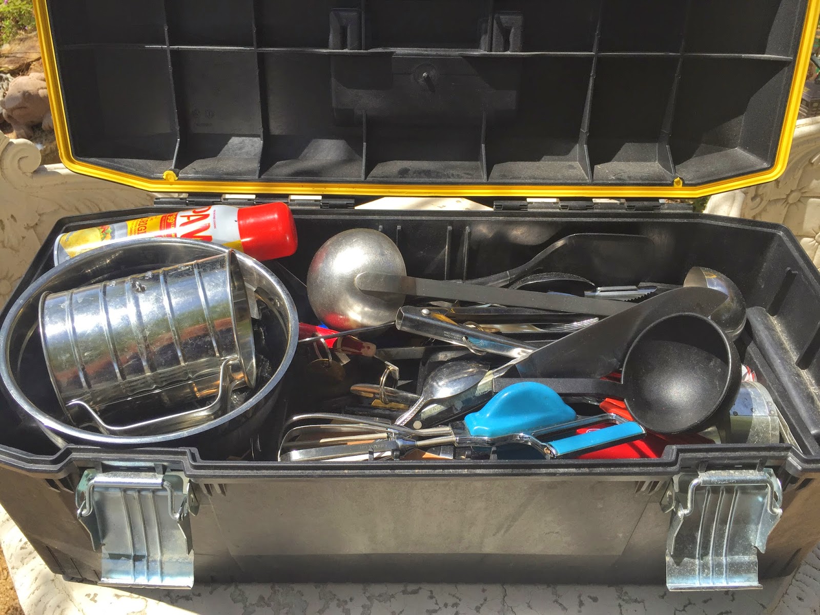
We use 2 Stanley Fat Max plastic tool boxes. They have a rubber seal, and latches. We leave them on the picnic table at all times (unless in bear country) and have never had the critters get in them. They also sit out getting rained on at times. When we return home the used items are replenished and kept inside so they are always ready to go for the next trip. Dry Ingredients such as flour, pancake mix, etc is rotated when we replenish. We dump the unused portion out on foil. Refill the used portion from new supply in the house, then dump the older ingredient now on the foil, back in on top to fill our camp container.
The cooking ingredient box has individual screw lid containers that contain flour, sugar, coffee, etc arranged in the bottom. Cheap containers found at your local dollar store. The tool tray sits on top of those and contains all the spices. The larger containers in the bottom have all their lids labeled with what is inside.
The utensil box holds all of our cooking tools. Knives, Sifters, Mini Cutting Board, Mixing Bowls, Whisks, Serving Spoons.
Here is a list of items in my two boxes. I cook with large groups and can cook or bake anything with what I carry.Adjust your items to suit your needs.
Spice/Flour Box
(2) Containers of Flour
Sugar
Coffee
Brown Sugar
Vanilla Coffee Powder
Buttermilk powder
Oatmeal
Cornmeal
(8) 1/4 Cup containers of Crisco
Spray oil
Salt
Pepper
Cilantro Flakes
Garlic Powder
Onion Powder
Italian Seasoning
Paprika
Corn Starch
Baking Soda
Baking Powder
Nutmeg
Cinnamon
Ginger ground/powder
Nutmeg ground/powder
Clove ground/powder
Burger Seasoning
Chili Powder
Cumin Powder
Vanilla Extract
Sage
Dry Milk
Cayenne Pepper
Bay Leaves
Vegetable Oil
Dry Yeast
Recipes on index cards in a small plastic zip lock bag
We extend a big Thank You to Lyle Guidry for sharing this DIY Project and photos appearing here.
A Galvanized Feed Pan from Tractor Supply was used for the sink. Also look at a similar pan at auto parts stores, Walmart, and others. Look in the auto section. They are used for changing oil.
The Pan has to have a hole cut in the center to fit the drain basket assembly. A hole saw works well. And make sure to use some plumber’s putty to seal the basket to the pan.
Cut a hole in barrel end with a sabre/jig/keyhole saw for pan to fit.
Any type of faucet would work. The type depends on budget and water source. If you have access to Hot and Cold that is one option. A single if maybe attaching to a garden hose? A hand pump to suction out of a tank? You might go as far as adding a 12V battery and 12V RV water pump for pressurized water? Connection parts will depend on your choice. Drill holes in barrel for your faucet and mount your faucet .
Plumb your drain to how ever you plan to drain. This could be a hose that drops into a bucket hidden in the barrel? Do you have a clean-out pipe on your exterior wall that is conveniently located? You may be able to screw out the plug. Screw in an adapter and create a drain to this location. If so be sure to incorporate a trap at location to keep sewer fumes from coming up your sink drain.
Plumb faucet to water source.
Cut out and create a hinged access door depending on the size you need.
I put a coat of marine grade polyurethane on barrel for protection
2010 Chevy Express Electric Lock – Sliding Side Door
Several step by step instructions have you pulling the interior plastic panel clear off. Then removing the screws that hold the whole lock assembly. Sliding the whole assembly toward the interior. I started this but was afraid of damaging the interior panel. Also the lock assembly seemed held by more parts than indicated.
The existing actuator is pop riveted on at two points. In my case I found my actuator broke off. The ears with the holes for the 2 rivets were broke off and the actuator was dangling inside the door. Hanging by the wiring harness.
To follow GMs procedure you would have to drill out the two existing rivets. Remove the old actuator. Disconnect the actuator from the wiring harness. Replace the part, then re-pop rivet the new actuator in place.
Disconnecting the harness is easier if you pop out the 2 plastic anchors that secure the wire inside the door.
My procedure requires drilling 2 small holes through the interior plastic panel. Rather than buying a pop rivet tool to re-rivet I opted to use bolts. After looking at the pop rivets supplied they did not have a large diameter head like the originals had. They are also heavier than the rivet tool I have. I also feared the pop rivets on the previous installation may have actually cracked the plastic ears of the actuator and started this whole problem.
My procedure allows minimal loosening of the interior plastic panel clips. I have tried my best in the past to remove door panels without damage. As carefully as I try I usually end up with a broken clip, or the plastic of the panel holding the clip cracks. While you do have to release some of them, we aren’t taking the whole thing off.
Before you start have the following:
Hook Pick to remove Door Handle “C” Clip
Flat wide pry device to pop the plastic interior panel loose
Electric Drill
13/64 inch Drill Bit
8mm flat Box Wrench
8mm quarter inch socket on a mini quarter inch ratchet
(2) M5-.80 x 20 Bolts
(4) 5mm Flat Washers
(2) M5-.80 Nylon Lock Nuts
(2) Plastic Panel Plugs (Auto Parts Store)
With the side sliding door partially open you will be working on the interior of the door.
Start by removing the interior door handle. It is held onto a spline shaft with a “C” clip. The shaft has a groove cut around it that the “C” clip locks into. I tried using a tool made for releasing these. A flat metal tool sold for removing handles. The problem here is the location is recessed and would not allow the tool I have to work. I found it easy to use a hooked pick. I pushed in the plastic cover behind the handle to expose the clip. Hooked the “C” clip and with a quick short jerk, pulled the “C” clip out. At that point the door handle pulls off.
Set the handle aside. I used some tape and taped the “C” clip to the handle so it didn’t go wandering off on me.
Using your flat pry device (I used a flat pry bar with a 90° bend on one end) gently pull on the plastic cover behind where you removed the door handle. This cover has a couple of clips. Completely remove this cover and set it aside
Pry the door interior panel at the vertical edge facing forward and about 2 clips worth along the bottom edge. I did not loosen any of the window plastic interior parts. Things will be tight but you should be able to work through the gap between the interior plastic panel and the metal door. Its awkward but doable.
You should now be able to see the lock assembly. The actuator is mounted on the side of the lock assembly…. on the side away from you, toward the exterior panel. It is pop riveted in two places on the lock assembly. The plunger end as a little “C” shaped plastic end that slides over a metal tab connected to the manual lock. The actuator is behind the lock assembly inside the door. You will have to do this part by feel. The actuator is also connected to a 2 wire wiring harness. The harness has a connector that will disconnect, but it does have a lock tab.
It is easier to disconnect the wire connector once you free up the actuator. If you use my method you will be drilling through the interior plastic panel. Locate the 2 pop rivet heads holding the actuator in place. Measure from some point of reference (Could be a piece of tape you use) and transfer the location of the rivet heads to the plastic interior panel.
Using the 13/64 drill bit, drill through the interior plastic panel at the two rivet locations. Then drill through these holes to drill out the 2 rivets. The lock assembly gives a lot so I rolled up a leather glove and jammed it between the back side of the rivet and the exterior metal door skin. The leather helped during the rivet drilling too. The rivets want to twirl with the bit and not drill out. Towels rolled and placed below inside the door will catch any falling parts.
Once the 2 rivets are drilled out, reach up inside the door and feel the end of the plunger. You should be able to easily slide the “C” shaped end off the manual lock tab.
At this point the actuator should be free except for unplugging the wiring. If it helps, pop out one or both of the plastic clips securing the wiring. These are inside the door cavity. It will give you more slack. But keep the routing of the wire the same. Disconnect the wire connector from the actuator carefully so you don’t break off the connectors locking tab.
Plug your new actuator into the harness and make sure the connector locking tab snaps to lock. At this point I would test your new actuator. You will have to close your door so the electrical contacts meet. (Temporarily stick your door handle on) While on the inside click your remote lock and unlock to check for travel on the actuator in both directions. If all is working, then proceed.
Slip a flat washer on one of the bolts. Hold the actuator in place and slide the bolt through from the door cavity through the actuator, then the metal of the lock assembly. Slip a flat washer on the interior end of the bolt. Then start one of the locking nuts on the bolt. With the flat box wrench on the bolt head inside the door cavity, and the socket/ratchet on the nut toward the interior, run the nut down until almost tight. This is very awkward and easy to drop a part or wrench. Have a rag or towel stuffed inside the door to catch anything.
Next reach up inside, and by feel slip the “C” shaped plunger end over the metal tab of the manual lock. Once you have this on repeat the procedure of adding a bolt through the 2nd hole of the actuator and metal lock assembly. Bolt with washer pushed through from inside. A washer and nylon lock nut spun on the interior end of the bolt. Tighten both bolts and nuts to secure the actuator. Do not over tighten and crack the plastic actuator ears.
Retest using your remote to make sure the actuator locks and unlocks the door. (Remember you have to close the door so the electrical door contacts connect).
Once you are satisfied make sure you reinsert any wiring harness anchors you may have popped out. If all is working snap all the interior door panel clips back into the door.
Then replace the cover behind the door handle. Be sure the manual lock slide engages and moves freely. Gently snap the cover clips into place. Recheck to make sure the remote works, as well as the manual lever, and also your key from the outside.
Place the door handle “C” clip in the slot of the handle. Position the door handle properly on the spline shaft. Then using the heel of your hand sharply jam the handle onto the shaft to lock the “C” clip into the slot cut in the spline shaft.
To finish the job plug the 2 holes with plastic panel plugs. (available at Auto Parts store).
Note: I labeled the GM Part number as well as the bolt head size in case I ever have to replace this again. Knowing the size of wrench to use will be most of the battle in the future since that bolt head is all by feel. The labels were stuck inside the door under the handle cover. The actuator I found broken was not an AC Delco. A GM parts person could not cross reference the sticker number on my old part. Nothing came up on the internet for the numbers on the old part. That same parts person would not give me the GM Part number either. He said he could quote price but not give the part number. The part quote was right at $200 and more with tax.
Little does that GM parts guy know he lost my service/repair business forever for this dealership. There are other dealerships in town…and I am one of those silent complainer types that just go elsewhere.
I found a blow up diagram on line and found what I thought was the correct part number. I found the parts on-line new in the $60 range.
While on Amazon I saw a used one for $22….and free 2 day shipping since I am a Prime member. I thought for $22 it was worth the gamble, and I would at least find out if it was the right part. Not a huge loss if I was wrong.
The part showed up two days later. Looked like new. AC Delco sticker and a GM Part#. In a AC Delco box. Instructions and rivets included. Though I already knew I wasn’t using rivets on my replacement. Best part was this $22 used part worked perfectly.
GM Part# 12362544 ended up being the part I needed.
12 inch Dutch Oven with Casserole dish that fits inside (Preformed foil type works)
3 Tbsp Flour
1 Can Evaporated Milk
4 Eggs
1 tsp Cilantro (Dried Flakes)
Salt to taste
Pepper to taste
½ Tbsp Butter
2 Large Cans of whole green chili’s
1 lb Cheddar Cheese shredded
1 lb Monterey Jack Cheese shredded
Instructions
Perheat 12 inch Dutch Oven 325°
Separate Egg whites from yolks (Keep both)
In large bowl combine Egg Yolks, Flour, Couple dashes of Salt & Pepper. Beat Well.
In another bowl beat egg whites until stiff. Fold egg whites into the yolk mixture.
Use butter to grease a casserole dish that fits in your Dutch Oven. Lay out half the chili’s in the bottom of the casserole dish. Spread the Cheddar Cheese on the chili’s.
Lay out the other half of the chili’s on top of the Cheddar Cheese layer. Then spread the Monterey Jack Cheese on top of that second layer of Chili’s.
Pour the egg mixture on top.
Bake for 45 minutes @ 325° or until an inserted knife comes out clean.
After having several cheap versions of the EZ-Up style canopies damaged because of wind, I set out to get a better canopy, and to fabricated a set of heavy duty stakes. Not something that would break the bank in the process.
I live in a desert and the soil is often a mixture of compacted sand and gravel. Any of the normally supplied stakes just would not work. Even some of the longer ones found at sporting good stores were ineffective. I know many of you stake down EZ-Up tent shade, and Chuck Wagon type canvas shelters. I also went to a commercial grade EZ Up brand canopy with straight legs. Even at places like Costco or Sam’s these commercial grade 10X10 canopies are in the $200 range.
These were put to the test on their first trip out. They were driven at an angle at the four corners. Then ratchet tie down straps were attached at all four corners of the EZ-UP, and tighten down. In the evening a storm blew in quickly. One of my friends EZ-Up’s stakes pulled out…that resulted in a mangled mess of aluminum uprights and ribs. Blowing around attached to the side of his trailer. His canopy went into the trash. Luckily his trailer wasn’t trashed in the process.
I couldn’t get my EZ Up down with that wind blowing. Nor did I think I could fold it for storage while working alone. I just made sure the straps were tight. The EZ-Up rode the storm out unscathed.
A set of four stakes will cost about $24 to fabricate (not counting paint and welding material). I happen to have a Mig wire welder which makes quick and clean work of the project. Gas welding/brazing would probably work just fine. If you are a good stick welder that will do too. Start to finish took me 45 minutes, including a quick coat of paint on the top end. These aren’t fancy, and I am not the greatest welder…but they certainly work.
These are made from Concrete Forming stakes and a few other common hardware items. I store and carry these in a old tent bag that has a zipper, and has 2 web handles.
Material:
(4) ¾”X24” Round Concrete Forming Stakes (The type with holes for nailing through)
(4) 3/8” nuts
(4) ¾” Flat Washers
(4) 1 ½” Steel Rings
Optional Fluorescent Orange Spray Paint
Tools:
Grinder or file
Welder or Brazing Torch
Bolt Cutters or Hacksaw or cold chisel and sledge
Channelocks, Visegrips, etc
Start by grinding or filing the round flat end of the stakes, and partially down the stake. This is to provide a shiny clean surface to weld. Also grind a small patch at the second hole down to provide a clean welding surface for the nut. Lastly grind about one inch at the point end if using an Electric Welder. Your welder grounding clamp will attach to the ground point end.
Cut the 4 rings with a bolt cutter, hacksaw or chisel. I did mine at the factory weld. Bend these cut ends slightly past each other and set aside.
Place one flat washer on a flat surface such as a brick. Hold the stake flat end down, inserted in the washer. Weld 360° around the stake end to attach the washer.
Flip the stake and weld the top of the washer seam were it meets the end of the round stake end.
With pliers or vise grips position the nut over the second hole which you have previously cleaned up with a grinder. Tack with the welder. Align and remove the vise grips holding the nut. Finish welding the nut to the stake. Be careful not to fill the nut hole with weld.
Slip the ring through the welded nut. Re-bend the ring to line back up. Weld the ring cut ends back together. Tack on one side, tack again at 180°. The ring should slide freely through the hole of the nut. The ring does not get welded to the nut.
Normally with a Mig your welds are not rough enough to need grinding. But clean up any sharp or poking points that might be protruding. The welds on the end of the stake at the washer will get hammered. They will soon flatten on their own.
I shot the top end with fluorescent orange paint so I can see them in the dark. Take a tennis ball (florescent) and slit it part way. These can be slipped over the stake after the stake is driven in. They are a great safety addition to help avoid a trip hazard, especially if kids are around.
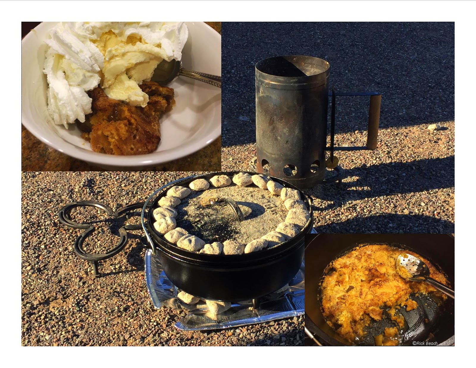
From our “First Annual Vintage Trailer Rally” @Lake Havasu State Park, Arizona. We managed to fire up the Dutch Ovens for the Potluck meal. Here is the Dutch Oven Apple Dump Cake Recipe:
1 Can Apple Pie Filling (Somewhat chopped)
1 Stick of Butter
1 Box Cake Mix (White or Yellow)
1 Tbsp. Cinnamon
3 Tbsps. Brown Sugar
1 Sprinkle Salt
8 oz Martinelli’s Sparkling Cider (Or Clear soda such as 7Up, Sprite, etc)
Start your charcoal 15 minutes ahead. 12 inch Dutch Oven – Apply a good coating of Crisco or Spray oil
Melt 2 Tbsps. of the stick of butter in the bottom of the Dutch Oven. Pour in the chopped apple pie filling and add half the Cinnamon, Half the Brown sugar and shake of salt.
Dump the dry cake mix on top of the apple mixture and spread evenly.
Chop the remaining butter in chunks and distribute over the dry cake mix.
Pour the Cider over the entire top of the cake mix best you can.
Sprinkle the remaining Cinnamon and brown sugar over the top.
Cover the Dutch Oven with its lid. Coals for 350 degrees heat.
With a 12 inch Dutch Oven, place 9 coals on the bottom at the outer perimeter. Add a full ring of coals to the top at the very perimeter of the lid (about 15 -18 coals.
Bake about 45 -60 minutes.
The cake should be somewhat firm on the top, but gooey when served. Best served hot with some vanilla ice cream and a little whipped cream.
If you like a sweet sour combination, serve with creamed cheese. Once it is cold I love it with a sharp cheddar cheese.
One of the most interesting old mine sites I have kicked around is the Techatticup Mine area, about 30 miles southeast of Las Vegas, Nevada. In current time it is host to endless settings of photo ops as well as a mine tour.
Prior to the late 1700’s this arid area near the Colorado River was home to several Native American tribes such as the Paiutes and Mojave. In the late 1700’s the Spanish came through in search of gold. The Spanish called the area Eldorado. They never found the gold and moved on.
Prospectors again returned to the area. Steamboat travel on the river had been established. Nelsons Landing became a stopping point. Nelsons Landing was a community on the Colorado River bank and would become one of the most active ports on the river. Up the huge dry wash several miles from Nelsons Landing, somewhere around the year 1861, gold was discovered. The Techatticup and Queen City mines sprung up. These along with some others, formed one of the richest mining districts prior to Nevada even becoming a State.
As you wander through old rusting vehicles and weather worn wood buildings you would never image this area as being one of the wildest western towns to ever spring up in the search for gold. Complete with double crossers, Civil War deserters, partner poisonings, gunfights, murder, and mayhem.
The area was also home to several notorious Native Americans that lived in this area. They also dealt in trouble and death. If interested, research Ahvote and Quehoe, or spelled Queho too.
There is a whole legend surrounding Queho. Along with Sheriff Frank Wait and posse attempting to find and capture him. The story would make a true western movie, but with a weird twisted ending. He eluded everyone. His mummified remains were to be found later by prospectors in 1940. In this strange tale, his remains where then put on public display until the 1950’s. He was finally laid to rest in 1975.
In today’s equivalent, billions of dollars’ worth of Gold, Silver, Copper, and lead were mined. There are miles of existing tunnels in the mountain at this site. Current owners, the Werly’s, purchased some of the area in 1994. They have restored many of the buildings and lead tours into the mine.
The area has been used as the setting for several Hollywood movies and TV shows.
If you are in or visiting the Las Vegas, Nevada area be sure to take at least a half a day and explore this area. If you have the time, follow the road down the hill to the gravel parking area at the base of the huge dry wash. Then hike a few hundred yards to the bank of the Colorado River.
At this location on the river, five large dry wash channels converge into a final small outlet where Nelson’s Landing once stood. In 1974 heavy downpours sent runoff water rushing down these channels. Some reports say the wall of water was 40 ft high. The entire landing and village were destroyed, washed into the river, killing 9 people.
2 cups unbleached all-purpose flour, plus more for dusting the board ( if you can get White Lily flour, your biscuits will be even better)
1/4 teaspoon baking soda 1 tablespoon baking powder ( use one without aluminum) 1 teaspoon kosher salt or 1 teaspoon salt 6 tablespoons unsalted butter, very cold 1 cup buttermilk ( approx)
Directions
Preheat your oven to 450°F.
Combine the dry ingredients in a bowl, or in the bowl of a food processor.
Cut the butter into chunks and cut into the flour until it resembles course meal.
If using a food processor, just pulse a few times until this consistency is achieved.
Add the buttermilk and mix JUST until combined.
If it appears on the dry side, add a bit more buttermilk. It should be very wet.
Turn the dough out onto a floured board.
Gently, gently PAT (do NOT roll with a rolling pin) the dough out until it’s about 1/2″ thick. Fold the dough about 5 times, gently press the dough down to a 1 inch thick.
Use a round cutter to cut into rounds.
You can gently knead the scraps together and make a few more, but they will not be anywhere near as good as the first ones.
Place the biscuits on a cookie sheet- if you like soft sides, put them touching each other.
If you like”crusty” sides, put them about 1 inch apart- these will not rise as high as the biscuits put close together.
Bake for about 10-12 minutes- the biscuits will be a beautiful light golden brown on top and bottom.
Do not over bake.
Note: The key to real biscuits is not in the ingredients, but in the handling of the dough.
The dough must be handled as little as possible or you will have tough biscuits.
I have found that a food processor produces superior biscuits, because the ingredients stay colder and there’s less chance of over mixing.
You also must pat the dough out with your hands, lightly.
DIY Project: Sliding drawer storage for Express Van
The objectives of this project were to first create Sliding Drawer storage in the rear of a Chevy Express van. The drawers are to ride on roller bearings to support lots of weight and for ease of use.
Additionally there will be a 30 gallon fresh water storage tank. This will be wired and plumbed to a 12 volt RV water pump to provide pressurized water.
Lastly the deck over the drawer space will be fitted with foam cushions and provide a comfortable sleeping area over 6 feet long and about 5 feet wide.
With some minor modifications this drawer system could be adapted for a pick up truck with a camper shell covering the truck bed, or various other SUV’s.
The project was started by creating some anchors for the wood deck. Electrical strut was attached to the van floor using eye bolts and the original seat latching pins that are in a Chevy Passenger van.. This provided a means to secure the wood to the van floor, and allows leveling with carpet shims out at the ends of the strut.
Two floating pieces of strut were attached to the underside of the far ends of the bottom plywood, at areas that have no seat floor connectors. These floating pieces of strut were shimmed to level using nuts and washers underneath. This installation allows the drawer box to be removed and the van returned to original, without drilling any holes in the floor of the van.
Right off the bat problems started. The threads of the eye bolts did not go far enough on the bolt shaft. It took 3 fender washers to make up the difference. I ended up pulling all the eye bolts out and used a thread cutting die to cut threads further down the shaft. After that these worked out with one washer as originally planned. This washer and nut will be recessed in the ¾ inch drawer box bottom panel. I did not want them sticking up any higher than necessary. I could have left the eye bolts floating, and eliminated that set of washer and nut. With the bolts rigid in place, it made dragging the drawer box assembly a lot easier…. to do the lining up, and dropping over the vertical bolts. A second fender washer and nut gets spun down on top of the drawer box bottom panel. This secures the box to the floor.
Positioning layout of water storage tank and RV On demand water pump. The tank and pump were already mounted in the van previously. It was originally mounted vertical, the long way, behind the 3rd row seat. (2nd & 3rd row rear seat have now been removed). Though the tank show here is flat on the wide side, it actually was installed with one of the narrow sides face down on the plywood. That way it took up less space I wanted for drawers. I did leave enough room to install the 12V RV water pump, and a full size AGM Battery. I also figured in a bulkhead and bottom stringer for that, using space in the water tank compartment.
Be sure to figure the passenger side clearance so that the vehicle jack compartment can be accessed, opened, and you can get the jack out.
At this point the assembly is about too bulky and heavy to handle by one person. Once I have the water tank positioned, the cross bulkhead panel, and attaching stringer locations were marked. This would eventually sectioned off the water tank area.
The shown assembly was then marked to saw cut out some sections of the bottom deck to lighten the load too. 4 dead areas of the wood plywood decking were cut out to reduce weight, but retain strength and leave material to attach all vertical partitions.
The assembly was pulled back out of the van. (Notice the protruding anchor bolts with no washers or nuts yet)
The cross bulkhead panel was installed to create the water tank chamber. A vertical center divider was run perpendicular to the bulkhead panel and attached to the bulkhead and the floor to create (2) drawer chambers about 22-23 inches wide. The end cap with drawer openings was then built and attached.
All panels are being screwed together in case this ever needs to be removed from the vehicle. Once the bottom panel was cut to lighten, the bulkhead panel attached, and the vertical divider screwed into place, this assembly was re-inserted in the van. The anchor bolts then have fender washers and nylon lock nuts spun down against the plywood deck. The excess threaded bolt lengths were ground flush with the top of the nuts.
The remainder of the wood construction will be complete inside the vehicle.
Roller bearing drawer guides were then installed on the inside of both sides of the box, as well as both sides of the vertical center divider. These will be skate board bearings part number 608-2RS. These are 8mmX 22mmX 7mm. Or about 7/8 inch OD X 5/16 ID hole X 5/16 wide. Some places want $4 to $6 each for these. I found them on eBay for about 40 cents each with free shipping, if ordered in lots of 100. I thought I might need 150 of them. So three days later my package of 200 arrived at my door step.
The drawer sides each have a 1×1 square steel tubing attached to both sides. This side tubing became the drawer rails. This tubing rail will ride on a long row of roller bearings, as well as a row of 4 on top (4 toward the drawer openings) above the tubing to support the extended drawer weight.
A removable “End Stop” needs installed through the very end of each rail after installing the completed drawers. (Drill a hole through the top end of the rail toward the very end of the rail toward the front of the vehicle. Weld this nut on the inside of the tubing end lining up the nut threads with the hole you drilled. After installing the completed drawers, screw a short bolt down into the threads of the nut. This will catch one the first of the top roller bearings and prevent the draw from pulling all the way out.
Next I needed to fabricate (4) 1X1 steel drawer rails. These would be mounted on the sides of the drawers, and ride on the roller bearings. I preferred to side mount mine. The steel tubing would true up the sides of the long drawers. Sigh….it is so hard to find straight lumber any more….even plywood.
I cut my steel tubing to length and marked off bolt placement. My design would require drilling thought the tubing with a 5/16 inch bit. Once all holes were drilled in the tubing I laid these out on my drawer sides. They were clamped into place, marked with bolt direction, marked top, and which side of which drawer these mated up with. Then I drilled through the holes in the tubing, and on through the side of the drawer. This was done because no matter how well you mark and drill the tubing, none of the holes would be consistent. The clamps were removed and brazing of the bolts was next on the agenda.
Carriage bolts were used to make sawing the heads off easier than using a standard hex head bolt. I insert the carriage bolts through the hole, brazed the bolt on the thread side. Then power hack sawed off the bolt head. Once the bolt head was removed I brazed this flush cut end to the tubing…finishing off that side by hitting it with grinder to make it flush and smooth.
Here I have 4 complete rails. They were matched up with the corresponding drawer side. Using a rubber mallet the bolt ends were pounded into the pre-drilled holes in the drawer sides. A flat washer and a nylon locking nut secured all bolts. The excess threads were sawed off and ground smooth with a grinder.
Not shown are the welded nuts inside the end of the tubing to act as drawer stop mounts.
Roller bearing placement was marked.
(4) on top starting 2 inches in from the drawer face opening, then every 5 inches on center.
(4) on the bottom exactly lined up with the four on top. Then bottom bearings every 12 inches. Toward the back add a couple that are spaced every 5 inches to carry the load when drawers are closed and you are traveling.
You want these two rows to be precise. Almost creating a clamping action between the top and bottom row, to secure the metal rail in between. You want no slop. Ideally when traveling down the road, the rail will have no room to bounce up and down. You do not want it to rattle or squeak.
The roller bearings are mounted using 5/15 inch bolts, nuts, flat washers, and nylon lock nuts. Those in the center are mounted on a common threaded 5/16 rod using lock nuts, flat washers, and nylon locking nuts. Excess threaded ends are cut off and ground smooth.
You may want to install more bearings on the bottom row depending on your intended load. The top row you want just the 4 shown, or your “stop” bolt will not allow the draw to come out far enough.
Shown above the drawers were rough fitted and work great. The drawers inside measurements are about 56 inches long, 20 inches wide and about 15 inches deep. ¾ inch sides and ½ inch bottoms. These are heavy duty. Made with 3/4 plywood.
At this stage, the drawers are roughed in and actually functional. I was able to test them out over a 3 day camping weekend. I loaded them full. There were Cast Iron cooking skillets, pots, tools, camp stove, etc. All this gear was heavy stuff. The intent was to really test out the drawers. The drawers worked great, even minus the drawer fronts, handles and trim.
I spend most of a day wiring and rough plumbing the fresh water storage tank. The fill tube and faucet are plumbed to the side door for easy access. Shown here you see a fill tube, pressurized faucet, vent, and a tank drain faucet. All the lines are run including the pump and connection to the 12V RV pump. As I said these are at the side door and overhang the step which has a plastic step liner. The backboard where the faucets protrude will be covered in tile, stainless, or aluminum. That way any drips or spray will end up on the step, and not on the carpeting.
Plumbing and wiring all hooked up. Tank partially filled. Pressure tested to make sure there are no leaks.
Shown below is the same area covered with white cracked ice finish FRP Wallboard. This is a non porous polyester resin material available from Home Depot. This was scrap left over from another project. It was applied with contact cement.
The images below show the completed drawer fronts. Pull handles installed. Also each drawer has a locking deadbolt latch to prevent the drawer from rolling back and forth during vehicle stopping or accelerating. I use a rubber “Door Handle Stop” on the front end of the drawer where it nearly touches the bulkhead. The Door Handle Stop acts as a rubber cushion or shock absorber. I have to apply slight inward pressure on the drawer handle to enable me to drop the deadbolt in place. This keeps the drawer from making back and forth noise, or deadbolt rattle, while driving.
The deck was fitted with individual hinged access doors over each drawer, the water tank area. Two dead spots along the sides that provide further storage, had drop in deck lids made. Finger holes were drilled in the hinged doors and slide in lids to allow easy access from the top too.
A 3 inch foam mattress on top of the deck was made in 3 sections. It provides an oversized bed. Configured to allow opening access to one half at a time (A drawer top or a compartment slid in top). Or access only to the water tank/pump/battery compartment.
The vertical panel facing front was covered with gray carpeting. Corners trimmed with ¾ inch aluminum angle. Exposed drawer fronts are to be painted charcoal gray to match the vehicle interior.