This post assumes you have some knowledge of electronics and soldering. It does not go into high detail.
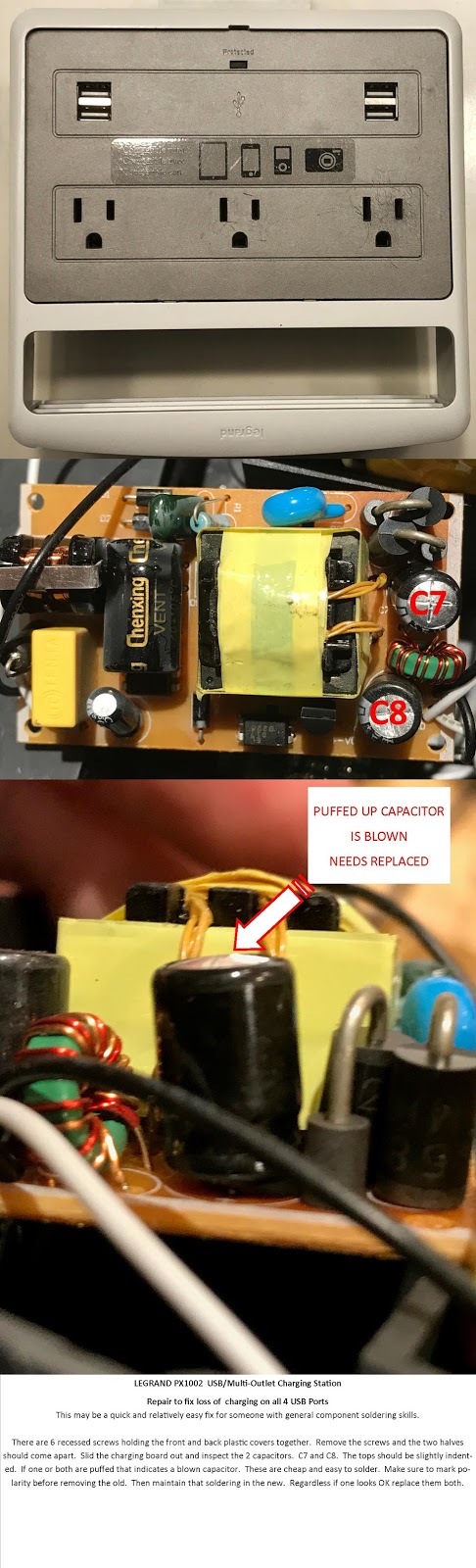
Recently my PX1002 stopped charging my USB devices. It came without warning, and without any visual indication. After my iPhone went dead, about half through the day, I realized the unit was no longer charging. The 110VAC outlets continued to work just fine.
I had purchased this at Home Depot a couple years ago. They no longer stock them. At least not in the local store I checked. Thought I would try a cheap fix.
Since all 4 USB outlets did not work, that narrowed the fault down to the little Power/Charger PC Board within the plastic housing.
From the rear of the unit there are six recessed screws. Remove these and the two halves of the plastic housing easily come apart.
Locate the board and inspect the capacitors. I found no fuses so capacitors are the next common thing to fail. The type used should be slightly indented on the top of the capacitor where the X in the aluminum shows. If one or more are puffed up it is a good indicator they are blown. There are usually 2 like valued capacitors. and various others. If either or both of the 2 like ones are blown replace both of them.
The one blown on mine is C7 which is the same as C8. Their value is 1000uf 10V . These are Hi Temp Radial Electrolytic Capacitors.
Depending on where you can find them to purchase they are dirt cheap. They are in the $1.00 each range. Though you might pay up to $4.00 each and shipping on top of that. Try to find a multi-pack with free shipping.
I found a 2 pack on eBay for $3.99 with free shipping.
My first venture into solar had me doing hours of research. My main purpose was two fold. First I wanted a system to use on an RV. Secondly just to satisfy my own curiosity. With a lifetime career in electronics and engineering I am always tinkering. So part of this project was self education. A “real world” hands on experience. I can see a bigger project on my horizon should this trailer project prove successful.
During research I found there are many systems, many components, and many so called experts. Some people making claims their system does such and such. Impossibilities using manufactures spec information I look up. I stopped arguing with these types long ago. I suspect they are running on their batteries storage and not producing what they claim they are. I touch on this for those looking on social media. I see stuff posted all the time that will lead you down the wrong path.
In hindsight I believe this fact many are misleading people, not purposely mind you. A
After designing and building a system and finding it performs very near specs and design, I truly do not know how people are coming up with some of their claims.
I found it difficult to pin anything down as being the “best” or “better” in all categories. Theory, numbers, and charts, are great but what really works when you start bolting stuff together?
I could have probably bought a cheap packaged deal to throw out on a sunny day… to charge up my battery. And I say “cheap” when I compare a $400-$800 plug and play system, to the custom system I built. It would either work or not work. That would be the end of my knowledge gain. Not much fun taking that approach.
Actually taking the approach to buy something that is inadequate, or one that under performs, is a big waste of money in the long term. Many in solar brag about numbers that only happen on the best of sun days. They don’t talk about those average days or even the bad days. I don’t know about you but my camping experiences usually come with the shade of trees, a good dose of clouds, and often rain.
In many cases going cheap or buying inferior products results in discarding those products and buying a second or third time. Most of us will probably admit over the years to doing just this, when buying computers. Once you get up and running you realize you should have purchased a faster model, or one with larger memory. Easy to do with solar if you don’t take a logical approach to knowing how much energy you will consume.
Then building or buying a system to provide those needs even on “bad sun” days. The day of the year, angle of your panel(s), shade, clouds, etc all need factored in. Design for the worst conditions if you need to rely on solar for power.
I don’t want to come across as an expert in solar by any means. But I do have about 40 years as a formally trained electronic technician and Engineer. Technical training and tons of practical experience with batteries, battery banks, charging systems, and component failures of all sorts. Batteries are a big component of this solar equation. They are probably the most misunderstood component in a solar set up too.
For the most part this is a search, and experience, is for my own knowledge. You get to benefit by following along. I will try to put this information into a non-technical format so that any half handy person might benefit from the info, my success, hurdles to over come, and my failures. Learn as I learn. I know the building blocks that need connected together. I also know some of the safety concerns many will choose to ignore. Perhaps not ignore but just don’t know because they pick up information from someone that doesn’t know.
For me it now becomes a matter of understanding the specs of these devices to produce what I calculate I need in the form of energy production.
Depending on how well this trailer project goes I am also exploring adding a small solar system to my house to power a 12/24 VDC evaporation cooling system to lower my air conditioning expense. This would be an “off grid’ system with grid system backup. I would not be going to the expense of tying in to the power company to receive power credits.
Based on what I have seen so far, the home power/cooling system might cost me $4000, including the solar & the DC powered Evaporative cooler. I estimate my air conditioning alone costs me an additional $1000 annually. So pay back on the system would be about 4 years. As the electric rates continue to rise this looks more attractive. I may shell out the $1500 for the cooler and run it off an 110VAC to 12VDC converter before jumping into to solar part. I initially want to see if the cooler can indeed do the trick? If it does, pay back will be 1.5 years on the cooler. In fact I may be able to adapt my trailer to power the cooler off my trailers solar, initially when the trailer is sitting at home? This is based on the cost of a 3000 CFM cooler rated at 120 watts/12VDC
GENERAL INFORMATION & DESIGN
My objective/budget is to build my initial trailer solar system for around $1500.00 $1000 for the components, wiring, etc. Another $500 for a custom rack system to span the width of my trailer. The total to be $1500.00.
Let me stop and touch briefly on the rack, or mounting system. There are items on the market less expensive in which I could simply attach my panels directly to the roof of my trailer. I just prefer to not make any holes in the roof skin.
The initial system is being built to keep two deep cycle batteries charged, and provide the ability to run my 12V 82qt ARB Fridge/Freezer. I want enough capacity to run the fridge perpetually while boondock camping for long periods. I want components that I can expand without replacing existing parts if I need to grow the system. Future plans are for a pure sine Inverter in the 2000-3000 watt range. (Update: The 2000watt inverter has since been installed and working great).
Major requirements
Stay within budget (it is important to realize the limitations of cheaper systems)
The system must produce enough power to restore my usage.
Produce that capacity with panels fixed mounted (I am not moving or adjusting panels)
Restore my usage in about 3 hours on optimum sunny days
Restore my usage even if the panels are in shade or during cloudy days
Restore my usage during winter months and shorter days/less light
Enough capacity to charge, and battery storage to bridge 3 days with zero production
HOW BIG DO I MAKE MY SYSTEM?
There are 3 major components. Solar Panels, Solar Controller Charger, and a Battery or battery bank.
The technical connections and hook-ups I found are relatively easy for someone with average hand tool experience, the knowledge and understanding of the use of a Volt-Ohm meter, and general electrical skills. The most difficult part for me was not the hardware end of this. It was trying to accurately figure out how much power I needed to generate, and how much I needed to store in batteries.
That boiled down to anticipating all the devices I would attach, accurately estimate how long each and everyone would be on in a 24hr period. That required some research looking up specs. After that it was all some math.
Toward the end of the article I was later able to “meter” the amp usage of each device when attached to my working system. I was happy to find the actual loads were slightly less than the specs stated. That was a plus!
You can scroll down and use my numbers to help you make your own calculation or guess-t-mate.
The first and most important step in designing your own system, and before you invest a single dollar for parts. Is to first calculate your anticipated energy consumption in a given 24hr period. Then research and design system parameters that will satisfy your needs. Don’t be frugal here to save a few bucks on your build. I doubt your energy consumption will go down over the years. Adding a larger panel or larger SC is not that much of an additional price tag. Trying to change out or upgrade later will be. This tech stuff changes fast. A panel you buy today, may not be around next year to be added on. An add on later may not be the exact dimensions to keep the appearance of your system looking professional.
I found a rule of thumb usage for the average RVer doing a weekend camp-out is between 30 to 40 amps a day (24 hour period). Further a rule of thumb system for the small camper doing weekend trips is around a 80 watt panel, a 10 amp Solar Charge Controller, and a single 12V Flooded Marine Deep Cycle battery rated at about 90-100 amps worth of storage capacity. But that is based on optimal sun. Also not factoring in bad sun days.
Ironically I personally use less than 25amps a day, but the 80watt system is too small for my needs. It would be fine if there was full sun everywhere I went. Those rule of thumb numbers are based on perfect sun conditions. I camp year round. Winter sun produces roughly half the power the summer sun provides you. That means Spring and Fall are somewhere in between.
This 80 watt panel and 10 amp SC (Solar Charge Controller) will output around 4.5 amps charging per hour. Of course this is under optimal sun conditions. During the summer you can expect a daily solar ampere (amps) output of about 28 amps on a sunny summer day, and about 18 amps during winter. That’s using (80 watt system) component values. Clouds, shade, haze, fog, rain, even panel dust, can greatly reduce this output.
If you need to cover more usage you need a larger system. 18 amps per day in the winter won’t cut if for me. I use 25….and the average RVer uses 30-40. I guess I am a more frugal user than most. If you only camp in the sunny summer for a couple of days at a time this may service you well? If you are very frugal you will be well powered.
I rate myself at a daily power use of about 25amps. So I want a system that will not only maintain on good days, but also be able to bridge through several bad days of sun. I also did not want to mess with re-positioning portable panels. Mine were to be fixed horizontally flat to the roof of my RV/Trailer.
I put this chart together to do comparisons for my design. As stated previously, I am a winter camper and also wanted the ability to bridge several days of bad sun due to shade or clouds.
If you start reading through all of this and say “a project like this it too big, or to technical for you to tackle”, or someone tries to convince you 40 watts is adequate, or someone attempts to sell you some wazoo system for big $, come back to this and read the next paragraph.
If you are the average summer time user, you can probably do OK with a pre-made system that has one 80watt to 120watt panel, a 10amp or larger Solar Controller Charger, and one 90 to 100 amp rated group 29 Marine Deep Cycle Flooded Cell battery. There are some nice portable packages. The panels fold and are protected during transport plus they have legs to angle the panels. Expect to pay in the range of $475 to $700 for a complete package. If you need the battery too, add on another $100 to factor in a Deep Cycle Flooded Cell battery. This won’t be real effective for winter camping though. It will more than likely not bridge you through several bad sun days due to shade or clouds. It will also not allow for expansion (More Wattage), without upgrading the Solar Controller/Charger. Be sure to do your usage calculation before buying anything.
BATTERIES
Before moving to the design stage you also need to understand batteries. This subject is probably the least understood by the novice solar user. Also highly controversial. The most misstated information found on forums and Facebook that can really misinform someone looking for information.
There are various types of batteries. First of all your standard 12V car battery needs to be eliminated as a battery option for solar storage. They are made to produce high “cranking” amps and are a poor choice for power storage. Sure they will work if you have to cut expenses up front but I suggest you do not use them long term. You will not be happy.
First Battery rule. Never mix Battery types (Spec size differences or Flooded & AGM) on your system. Yes, and many will say they do it all the time without mishap. I won’t say more here other than “I wouldn’t do it”! I have been in the business too long and seen this too often. This battery subject could create an article longer than this one on solar.
Be aware this includes connecting your tow vehicle battery and charging system, to your trailer system. If you do connect up this way, don’t mix “Flooded” and “AGM/Gel” batteries together via those connections. Beyond my safety precaution, you can make your own decision. 12VDC at the high amperage a single battery can produce, is capable of welding metal, burning things, causing a fire, or exploding a battery.
Mixing battery types on a single “charger” can create a catastrophic condition called “Thermal Run Away”. Look that up if someone tells you to hook up dissimilar batteries to a charger. This one I have personally witnessed the resulting damage.
Those not heeding the basic rules often find out the hard way.
The least inexpensive Battery that will get it done!
12V Marine Deep Cycle Flooded cells are the first reasonably priced option for solar energy storage for RV’s. Weighing cost, performance, and requiring little knowledge to set up. In my opinion they give you the biggest bang for your buck. Especially start up cost.
They are readily available on the road should a replacement be needed. Especially good if you are not real technical. If you move to the other type of batteries you need to be armed with more knowledge than just connection wires to the proper polarity.
Flooded cell type are cheaper. But you have to maintain the water levels. You also have to mount them outside, or seal them in a case that is vented to the outside. The put off poisonous and explosive gases.
They are compatible if connecting your system to your tow vehicles electrical system which has a flooded cell battery, and an tow vehicle alternator that produces the same “Absorption charging voltage” required by both tow vehicle and trailer batteries if all are “Flooded” types.
Often Trailers have a 110VAC to 12VDC Converter/Charger for use in RV parks that supply “park power” . In many the Converter/Chargers Chargers are fixed to output 12VDC for flooded batteries. Multi-phase “Smart” chargers outputting “absorbtion charge voltage” for Flooded. These are the WFCO and Progressive Dynamics Converter Charges.
I am sure technology is changing to make these switchable or adaptable to charge one type, or the other. The point being, you better know for sure….and you still will not be able to attach dissimilar battery types to the same charger, at the same time.
AGM’s More amp storage, costs more, and you better understand tech specs
AGM type are sealed batteries. Theoretically no venting is required. These are not what are referred to as Flooded.
You don’t have to maintain water, and they can tip over without damage. Many will argue the AGMs are the better choice…but they are more expensive, and have charging limitations, that I am not going to get into the technical end of right here.
The AGM’s are great if you are not connecting your trailer system to your tow vehicle’s electrical charging system. Creating what is commonly referred to as “Stand Alone” system, or “Isolated System”. They require you have more knowledge of your systems charging device specifications, and controls, etc.
They do require charging devices that put out the specific “absorption charging voltage” for AGM type batteries. Many existing RV electrical systems you might be connecting to, including your 110V to 12V DC Converter/Charger, may not be possible to set up this way. They may not even have the options to adapt. More on this comes up further into this article.
There are other battery options
There are other Flooded Battery options that provide better storage such as two 6V golf cart batteries wired together to equal 12 volts. They can store a significant more amount of energy/amps than 12V Flooded Marine batteries. Again they come with a higher price tag. Weight also becomes an issue.
There are other set ups that use other voltages such as 24V systems. I am not going to discuss those since they are not the norm for the regular RVer, trying to easily integrate that type of system with the 12V system of your tow vehicle.
There are Gel Cell, Lithium, and who knows what else on the market, or coming soon. If you branch off into this realm you better have a good grasp of the technical end of things, the proper chargers, and safety precautions followed attempting to integrate your trailer, your solar, and your tow vehicle.
Battery type choice is like discussing religion or politics. So I leave that choice up to you. Arm yourself with knowledge then go with what works best for you. Much is dictated on how fat your wallet is. The most cost effective start up, with no technical charging issues to deal with, in my opinion, would be the 12V Flooded Marine Deep Cycle.
I considered all of this and elected to go with 12V Marine Deep Cycle Flooded cells myself. My Brand of choice was the Interstate group 29 Marine Deep Cycle. More a choice due to cost and availability. Plus the fact I was wiring them in parallel with other existing “flooded” cell batteries through my tow vehicle wiring system. I also connect my rig to my tow vehicle which also has a “flooded” 12V battery. I refer to this configuration, as having an “Integrated Solar/Trailer/Tow Vehicle System.
The cost of my batteries was right at about $80+tax each. $95 each if you factor in the $15 core charge per battery. Interstate Brand at Costco.
A little more about batteries that many people are not aware of.
When connecting batteries together to charge off a charging source such as a Vehicle Alternator, some type of home, park, or generator powered 110V AC to 12V DC converter/charger, or a Solar Converter/Charger you need to use like batteries. Batteries that take the same type of charging voltage.
You have to consider your tow vehicle alternator, and your other types of Converter/Charges, which include the 110VAC to 12VDC types, as well as a Solar Converter/Charger. Most all of these are able to produce the charging voltage for “Flooded” type batteries.
Most AGM’s require a lesser “absorption charging voltage”. This difference can cause issues if mixed in and connected to dis-similar types. Most people forget to factor in the fact their tow vehicle is often connected. With the tow vehicle alternator running, the alternator connected in via wiring, it is doing charging. That tow vehicle alternator is designed to charge at higher “absorption charging voltage” for flooded cells.
If you have some type of stand-alone system that is a whole different set-up. We aren’t going to discuss that since that is not the typical configuration for a RV/Trailer that connects to a tow vehicle.
You should never, ever discharge your “Flooded” battery beyond 50%, and many others including myself do not discharge less than 60%. Running a battery dead or nearly dead will damage the battery to the point it will not charge and stay charged, or it will rapidly decrease the life span of the battery. You may not even know if you are below 50% without a meter. Things keep working….for awhile…even a long while if relatively low amps are being drawn continually.
One of the main culprits of drained batteries of an RV is the Propane/CO detectors. People park their rigs for storage without keeping a charger going on the battery. Those detectors will suck every amp of storage out of your battery over time. Even batteries not connected to anything slowly degrade in stored energy over time. All of this can lead to partial or total battery damage. If you don’t like the idea of a charger on all the time, install a battery Cutoff switch. The Cutoff switch is great for when in storage. But occasionally top the charge off. I check mine monthly.
A 12V battery is normally charged at a higher “Absorption Charge Voltage”. So if you tested a fully charged battery with a voltmeter you might read somewhere higher than 12 volts, probably as high as 14.6V. Not 12.0V as many assume a fully charged 12V battery would read.
Ironically, when a 12V battery discharges from its full charge……down to 12.0V, that battery is actually real close to its 50% discharge. There are charts and methods for measuring what is termed “Standing” or “Resting” Voltage. The info is easy to find doing a web search. Normally the battery is tested after all loads are removed and it is allowed to “Rest” for a period of time. Another method in the case of flooded cell batteries is to check the cells using a Hydrometer. But the Hydrometer is not real convenient for some when out RV’ing. Useless if you are using AGM.
So now knowing you should never use more that 50% of the charge in a battery that gives you other factors for your design. Those $80 Marine Deep Cycle Flooded cell batteries might be rated 85 to 100 amps each. Lets assume its 100amps each (Makes the math easier) If you have one 100amp battery that is fully charged you get to use half of that (50%) for your use, or 50 amps. At that point it needs amps put back in (re-charged). If you couldn’t recharge it, or charge it back to 100%, you could keep using the energy stored running lights, inverter etc. But once you drop your battery below 50% you are doing damage whether you are aware or not….and yes your lights and devices will continue to work for some time, sucking out the remaining storage energy. That drops the battery voltage reading into the battery damage zone. A meter is necessary to give you an indicator. If you wait until devices quit working it is too late.
Those that have been out camping for a weekend and running off their trailer battery and all of a sudden the lights and things stop working….most people think charging back up is all it takes. Nope, you may have really killed that battery, or it may never fully charge, or not hold a charge very long. It is important you know that status of your battery charge all the time. It takes meters or indicators that can be inexpensive or more sophisticated.
Meters can be wired into the system. Others opt to have a plug in type that plugs in the a 12V DC cigarette lighter type receptacle/socket. Many RVs have such a socket already available. It is also a fairly easy project to add one of your own.
The better meters give you 3 essential readings. (1) Active AMPs which display both positive, and negative digitally. That way you know if you are charging or draining, and to what degree in amps. (2) Current Voltage of the battery. Remember not to go below 12.0V. (3) Percent % of battery charge. Never go below 50%, more preferably 60%.
If the average RV camper uses 30 to 40 amps in a 24hr period, and they just have one auxiliary trailer battery with no means to recharge, a 100amp battery is going to go beyond the safe zone, into the danger zone, somewhere during the second day (remember you only get 50 amps to use). If a person could limit their usage to 25 amps a day, they would get 48 hours off that 100 amp battery without damage before needing a restoring charge. This leads back to how much power will you consume, and how many batteries do you want on your system? If you need more amps, you need more battery storage capacity….and more panel wattage to fully charge the batteries.
I wanted charging capacity at least 3 times my calculated usage
My total system design then went to about 3 times the rule of thumb for a weekend camper. About 3 x 80 watt panel=240 watts of panel. The panels I wanted where 140 watts each so I started with (2) 140 watt panels for a total of 280 watts worth of capacity. Remember I want the ability to bridge 3 days of bad light. Basically bridge 3 days of no light.
My Batteries are two 100amp each Marine Deep Cycle flooded cell. So 2×100 gives me 200amps of battery storage….and that gives me 100 amps I can use if I adhere to the 50% recommendation. But I adhere to 60% so that allows me to use 80 amps before I need to start charging more juice back into the batteries.
I found my real life power usage is slightly under 25amps in a 24 hour period. That pretty much matched the calculations I had done for myself. So the 80amps available from my two batteries should theoretically last me slightly over 3 days or 72 hours. That bridges me through 2 extra days even if my panels produced 0 amps. This satisfies my 3 times objective for my system. Even on the a crummy sun day I have never dropped down to producing 0.0 amps with no load on the system. I may have dropped in the negative though with devices running and using power.
Additional info for selection of your battery. If your Trailer Auxiliary battery will be wired to your tow vehicle as well as your solar controller/charger, and more than likely a shore powered 110V AC to 12V DC converter/charger, consider this. You will have 2 batteries connected in parallel whether you realize it or not. Your Auxiliary Battery and your Tow vehicle battery. Though some vehicles have an ignition relay that opens this connection when the key is in the “OFF” position in the tow vehicle. Others do not.
It is good practice to use similar type batteries with similar specs when wired together and charging off the same source(s). This makes components compatible depending on what charging source happens to be providing the charging voltage at any given time. This may be your tow vehicle alternator, your solar charger, or your shore powered converter/charger.
Flooded cells require an initial charge voltage (Absorption) of 14.6V that drops to 13.2V during the “float” mode.
AGM type require an initial charge voltage (Absorption) of 14.3V that drops to 13.2V during the “Float” mode.
Some Solar Controller Chargers have settings or jumper straps to set them to charge for a “Flooded” or an “AGM” Some shore powered converter charger devices may have this ability to program or set the charging output. My shore powered charger does not have this option. But again, if you incorrectly mixed battery types, which charger setting would you select? The ‘Flooded” setting could over-heat and damage a AGM battery. A “AGM” setting would not properly charge a Flooded battery.
What happens if you mix and wire together an AGM auxiliary battery with your tow vehicle “Flooded” Cell? One of the batteries is not going to be charged properly. Even your vehicles alternator and internal voltage regulator is set to output the higher “Absorb” voltage since most vehicles use “Flooded” Batteries. More than likely your shore powered Converter/Charger is sending out the higher absorb voltage since most RV trailers are set up with a Flooded cell battery too.
If you set your Solar Controller/Charger to output the 14.6V “Absorb” voltage to properly charge a “Flooded” cell, that additional voltage may overheat the AGM that is wired in with the “Flooded” cell. Sure it may work and not appear to have a problem. But in hot weather it may result in a damaged AGM. It might crack due to excessive heat that builds up during charging at the higher “Flooded” cell “Absorb” voltage of 14.6V. Any of this could result in a fire. Damage may take some time or it might happen quickly depending on conditions. ….and yes, you might be one of the lucky ones doing this that can say “it has always worked for me”.
Even your tow vehicle alternator that is attempting to charge the tow vehicle “flooded” cell, is going to be applying the higher voltage to the AGM that is back in the trailer. That’s if it is connected in, as many trailers are.
So in my opinion I would never mix wiring batteries together that have different charging specs. If you are going to use AGM make sure you know the “Absorb” charging voltage output of all your charging devices. If using AGM batteries in your trailer I would isolate that from the charging system of your tow vehicle. Do you have the ability to set or program all your charging voltages, or does the device at least auto detect and regulate to the proper level depending on whether a “Flooded” or AGM is attached? Is the AGM isolated from any “Flooded” cell connection? Make sure any secondary battery is a similar match so they both charge at the same rate.
The Solar Controller Charger
Be aware there are different types of Solar Controller Chargers. The two common types are the MPPT (Maximum Power Point Tracker), and the PWM (Pulse Width Modulation)
The PWM is for smaller systems and is a less expensive device. You can achieve great results with a PWM and a single panel or even several panels. The system and the Solar Controller Charger I am using and discussing is a PWM. (The brand and model I use does require the panels are 36 cell)
The Solar Controller Charger, sometimes referred to as SC is wired between the solar panels and the batteries. It takes the fluctuating voltage/amps being generated by the sun and panels, and regulates it to a constant. That regulated voltage/amps, is outputted by the charging part of the SC device, and applied to the batteries. Without getting too technical, that charger has different “stages”. A “Smart” Charger. It senses how full or discharged the battery is and adjusts accordingly….eventually when the battery is charged, or full, it settles into a lesser charging voltage mode known as “Float Mode”. The “Float” mode maintains the battery at its fully charged state.
A note on Solar Controller chargers. Some have the ability to be programmed to produce even higher voltages than your standard “Flooded” output “Absorption Charging Voltage”. This is a more advanced technical capability.
Most non changeable, or non programmable, Solar Charge Controllers, and even the better multi step chargers put out a fixed higher “absorption” charging voltage (the Flooded type charge voltage). In most devices this “absorb” voltage is a set value and not adjustable. The standard voltage, if your charger can be set to that, isn’t really enough to charge fast, and really isn’t enough to completely top off flooded/wet cell batteries to 100%. Over time the slightly under charged flooded batteries will deteriorate faster than batteries charged to 100% Slightly undercharged batteries will also store less energy than a battery that is charged to 100%. Even a loss of 5% is a tremendous loss of potential stored energy you could otherwise tap for use.
So I found a SC that was programmable to put out an even higher “flooded” charge voltage, should I wish to go there. It gives me that option whether I use it or not. I certainly would not be outputting this voltage to AGM type batteries. Should you use this higher “Flooded” charging voltage, (along with flooded batteries) it requires the addition of a battery sensor that is connected back to the Solar Controller/Charger.
To some this might cause a huge debate. Perhaps running the “Absorb” voltage at 14.9V on a “Flooded” cell. This creates a charging heat inside the battery. As stated this further requires the use of a battery sensor that is interfaced with the Solar Controller/Charger. Those that have issues with this can do further research into the more technical aspect of some of the SC’s. People running solar are successfully storing more energy using this method.
For the purpose of discussion and my initial charging set up I am not programming my SC to output higher non-standard charging voltage. Though the Battery Heat Sensor is wired in for future use.
For my Solar Charge Controller I purchased: A TriMetric SC-2030 Solar Charger.
The SC-2030 is a Solar Charger for either a 12V or 24V system and rated at 30amps. The unit will work on flooded, or AGM/Gel Cells (They come pre-set for “flooded” cell batteries). The Unit also has the ability to be set for the other outputs in less than a minute. Pre-sets on 12V are:
Flooded/Wet Setting =14.6V Absorption and 13.2V Float
AGM or Gel Setting =14.3V Absorption and 13.2V Float
Since I am using Flooded batteries the little Solar Controller option switch is set to “FLOODED” My system is 12V so the other little Solar Controller option switch is set to 12V. Its that simple for the initial set up.
The Solar Panels
When looking for Solar Panels look at their specs. If you are building a 12V system, get panels rated for 12V. There are others that produce different voltages. Watts can vary depending on your preference. Dimensions also depend on the area you have to work with. With the Solar Controller I used, it specifically stated it should be used with 36 cell panels. If you use other components be sure the spec requirements all match up.
For surface area, my thought is to get the highest possible wattage for the roof real estate you will be using. But cost may be an issue. Many say the different types of panels made today are relatively comparable in performance. Start shopping for Price per Watt if price is a big factor. There are used panels on the market, though I didn’t use those. From research and testimonies, I tend to believe American made, or Japanese brand panels, are of higher quality. This is where your own personal research comes into play. You have to jump in somewhere.
On a 12V system make sure the panels are 12V rated, and rated for charging batteries. My Solar Controller Charger required 36 cell panels.
Look for the VOC spec. VOC should be in the range of 20 to 22 Volts. VOC stands for “Voltage Open Circuit”. It is the measurement with a meter across the output panel voltage, in full sun, and no load connected.
Next make sure the VMP spec indicates it is rated between 17 and 19 volts. VMP stands for “Voltage Max Power” So rule of thumb, for calculating using power formulas, your panel voltage number will be 18 volts. (18 is the middle ground of the 17-19 volts)
Then look at the Watt rating. Use the power formula below to figure the amps it will generate.
Power Formula P=IE
P=WATTS
I=AMPS
E=VOLTS
i.e. a 140 panel with full sun….how many max amps would be available?
Divide the Watts by 18 for a rule of thumb AMP rating.
We know the average Voltage output is 18volts (18=E in the formula)
So with P=IE P=140, I=unknown, E=18) or
140=I*18
I=140/18
I=7.7 (or 7.7amps)
Just remember this is an average of the maximum of your panel(s). They will not always be cranking out this type of electrical energy.
Also of note. Your Solar Controller Charger must have an AMP rating higher than the max output of all your panels. If your panel or panels produces the average max amps of 7.7 you would need a controller charger rated at least 10amps or more. Technically you should not use the “average max” for the Controller selection, but figure the “highest possible max” amp calculation.
If you multiple panels in parallel, the voltage will remain the same, but the amps will add together, which in turn will require a higher rated Controller based on the “highest possible max” amp calculation.
Additionally, if you put a 10amp Solar Charge Controller on this 7.7 amp calculated panel, you won’t get 10amps out of a 10 amp controller as some people think. The SC can not amplify, or increase, the produced energy coming off the panel. There is only 7.7amps available off the panel. So you will only produce 7.7amps coming out of the SC for charging purposes.
I am guessing there is some inherent loss associated with the SC too, and those output values would even vary slightly. Plus we are not factoring voltage loss associated with wire gauge or length that will occur between your panels and the SC unit. Also remember the panels angle and the brightness of the sun all affect the output of a panel. Even a coating of dust on your panels has a negative effect. They often will not be producing at 100%….probably never. Expect and plan for somewhat less.
So think of the Solar Controller Charger rating as the input capacity/limit. The amount of input amps that can be connected to it from a panel without burning it up. Don’t think of the Controller/Charger rating as the output amps.
The panels I selected can generate 7.7 amps or about 7 to 8 amps each at a maximum. I am using two panels so when they are wired together they could output 14 to 16 amps. A 10amp SC could not handle the higher 14 to 16 amps. I selected a 30 amp SC. That also gives me the option of adding a third panel in the future without the need to upgrade my 30amp SC.
In my case I also wanted a J-box (Junction Box) mounted on the solar panel. I wanted to stay away from proprietary type connectors. Stuff that breaks, hard to find, Special tools required. Keep it simple. The Solar Panel I ordered is a 36 cell Kyocera KD140SX-UFBS 12V 140 watt Panel with Junction Box. There is a screw down terminal strip in the box. I wanted max wattage, and simple connections. This panel is also the largest that can be shipped via UPS Air to your residence.
You need panels rated for charging batteries. Panels with specs outside this range may or may not be designed for charging batteries. This panel is rated at 12V, 36 cells, 140watts, VOC=22.1V VMP=17.7V and comes with a standard Junction Box for terminating the power wires. I did not want special connectors to contend with, try to mate up a wiring harness, or try to replace/repair during trips.
Cost including Priority Shipping $315.49 per panel
Meter Monitor – Shunt – Battery Sensor
While a system meter is certainly not necessary for the system to function you would quickly want a way to know 3 things.
The Voltage readings of the Battery
The Amps (either being generated or used, or a combination of both)
The Percent (%) of charge on the battery
The TriMetric TM 2030-RV will give me a remote monitoring ability to meter and see what is happening with my batteries and charging. This remote will also provide the ability to alter the charging voltage to the higher settings within the Solar Controller Charger (SC-2030) I will be using, to insure my batteries are charged to 100% and not to 95% or something else less than 100%
The meter I went with, as stated, can program the SC to change charging voltages.
A shunt is required to run voltage sampling leads to provide the various readings on the meter. I ordered a 500 amp shunt.
I also added a Battery temperature sensor that is hardwired into the SC. This is an override in case the batteries become overheated by external temperature or internal due to over charging voltages. Once a critical temperature is reached it will cause the SC to shut down charging from the SC unit. This is an added safety.
Major Component Summary
Kyocera Solar Panel = Converts Sunlight to Electric (Has J-box)
SC-2030 = Solar Controller & Charging
TM- 2030-RV = Remote Meter and Control of the SC-2030 Charger
Battery =Storage for your generated power, and powers your devices during no light
Battery Temperature sensor at battery wired back to the SC-2030 for control
500 amp Shunt allows connection of meter wires for voltage, amps, and % readings
Perhaps over kill on the charger and shunt, but I want to be able to add more batteries, more panels, and an inverter in the future. I do not want to change out components if or when I upgrade.
As I indicated I also want the ability to adjust the charger output voltage. To increase it from a fixed max voltage to a higher voltage to match up with the Battery specs max charge rating of a Flooded/wet cell…..pushing nearer the 15V range during initial stage charging….overriding the default of around 13.8V for a flooded cell. In float mode it reverts back to a standard 13.2V.
The SC selected also can adjust in the case of AGM battery use, to a lower “Absorb” charging voltage. I am talking in general about the Absorption charging voltage since the Absorption charging voltage and Float charging voltage differ even within a given charger. Those charging voltages also differ with each battery. Get your manufactures specs on your specific battery. Even getting 5% less of a charge greatly reduces the stored energy you will get to withdraw to run your electrical devices. If multiple batteries are connected together make sure they have similar specs. Don’t mix “Flooded” and “AGM” on the same charging device. At the very least you will get less than optimum charging.
You do have to know your devices that are plugged in can handle any additional charging voltage changes should you start tweaking the SC and raising the “Absorb” charging voltage.
Those that dispute my thoughts on adjusting the charging output can research on their own, then come to their own conclusion. Check the battery specs of what you will be using. Other people may sight that this increase in output charge voltage will overheat the battery….hence the battery temperature sensor that also connects into the SC-2030. The connected temperature sensor further overrides any charge settings the charger is following, should the battery become too warm.
Many using solar are reaping the benefit of this additional charge voltage. I am only trying to get max charging when my panel(s) is/are converting the suns energy. To store that energy as quickly as possible. I am only passing on what I am doing, and things I learn along the way. I am not trying to trigger a debate on chargers, voltage, or batteries.
Parts Purchased from & Source of Solar vendors.
BACKWOODS SOLARThey have a great catalog that is packed with all kinds of info such as wire gauge voltage drops, as well as what they sell. They are helpful over the phone and can supply all your solar needs. They have a catalog they will send you, or visit their website and download a PDF version.
NORTHERN ARIZONA WIND & SUN I purchased my solar panels here. I had called a company in Massachusetts first. www.altestore.com When they quoted me shipping to Nevada I said wow! They then actually recommended I call Northern Arizona Wind & Sun since they are much closer to me. Hard to find a business willing to do that…my hats off to them as well. It also made me feel like NAWS would take care of me with that recommendation. That proved to be true also. I paid a little extra for 2 day delivery. If I lived on the east coast you can bet I would be using www.altestore.com
In hindsight, knowing what I know now, I would purchase the bulk of my components from Northern Arizona Wind and Sun (NAWS). They are competitively priced, excellent customer service, and ship fast. Also for me they are in driving range if I absolutely had to make a trip.
Since the first panel arrived and I had the opportunity to test it and make sure it was the one I wanted. I then ordered a second panel. It has since arrived and has been tested also. NORTHERN ARIZONA WIND & SUN was great to deal with. Both panels arrived unscathed (I have read of horror stories on panel deliveries). They were at my front door in 2 business days.
Various other parts such as terminal posts, battery switch or ignition switch, and DC Breakers were found and purchased off the internet. Local prices were 10 times the cost or I couldn’t even find them. On line stores selling marine products are a great source to start looking.
How do you mount the panel – Custom Rack Fabrication
Mounting your panels will be another personal choice. There are a wide range of tracks, clips and other mounting hardware. My panels were going on the roof of a trailer. I wanted an air gap between the panel and my roof. These panels get considerably hot. Especially here in the desert southwest where I am located.
I also did not want holes of any kind in the top of my trailer. But I also didn’t want the whole contraption blowing off as I drive down the road. My weight estimate of a rack, 2 panels and assorted pieces of hardware for electrical and mounting came to about 140lbs. That also meant I had to fabricate it in such a way I could get it on the roof and situate it.
I opted to build a rack that would be mounted to the rain gutters. I had to span about 8 1/2 feet and used 1×1 and 3/4×3/4 16 gauge steel tubing.
I chose to gutter mount mine. Then further secure that vertical gutter bracket by drilling through the bracket, through the side skin of the trailer, and into the trailers metal frame. A self taping stainless screw was driven through the gutter bracket and secured into the trailer frame.
I had several designs in mind to construct the gutter clamps. After pricing material and hardware at Home Depot I found it easier and probably nearly as cost effective to purchase heavy duty pre-made clamps from Smittybilt. I purchased these at 4wheelparts. This just made my fabrication easier and faster.
I used their Defender series Rain Gutter Clamps (P/N: S/BHDS-4) That got me (a set of 4) clamps and hardware for $104.99. The 90° metal part that would be used to attach their rack was discarded. The clamp back plate modified by welding it to a piece of of flat steel about 14X3 by 1/8 inch thick to create a vertical upright. The cross member 1×1 steel tubing welded to the uprights.
The roof line high center point requires 12 1/2 inches of clearance from the rain gutter to the bottom of the cross bar tubing. This clearance measurement includes a 2 inch gap in case of flexing during travel. The uprights will be left high enough to allow stacking a second 1×1 cross member in case the 8 1/2 ft span is found to flex too much using only one cross member. Once weight testing is competed with the basic bar and rack, the additional 1×1 crossbar will be added if required, or the uprights trimmed and finished with the one cross bar.
Note: It was a good thing I anticipated the fact I might have to double up the cross member. I had made my vertical extra long just in case. The vertical risers ended up being 14.5 inches high. My cross members are 100.75 inches spanned across the width of the roof. The cross member with just one 1×1 tubing flexed too much. Adding the second 1×1 tubing beefed up the cross member nicely. My solar panels weigh 35 lbs each so there should be no problem supporting 70 lbs. If I were fabricating this frame from scratch again, I would use 1×2 tubing for the cross arms.
Vertical Riser Welded to the Gutter Clamp
Vertical welded to Crossbar and 45° Brace
Rough finished rack component
Welding the Gutter Cross Arms together to create a square mount
Primer and Paint
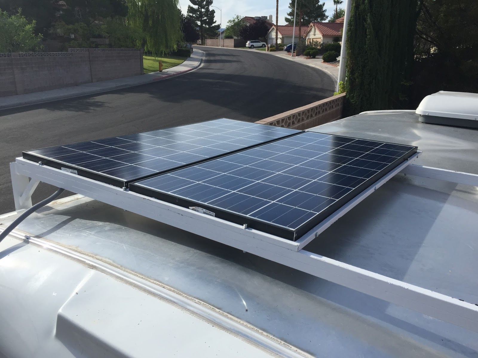
Rack Mounted and secured
Panels and Conduit in place – Wires all terminated
Regular EMT was brazed together to make the conduit water tight
The power board (Build it modular)
Layout was started with the major components and wire terminations
Shown above is the solar charge/controller (upper left green & black device). Two 40amp DC circuit breakers on the cables that will connect to the solar panel feed. The black and gold device in the center is a “shunt”, necessary to provide metering capability. A third 40 amp DC breaker is shown toward the bottom in the “Positive” Battery cable run. Then there are five terminal posts that the various power/battery cables will be connected. This board is built as a module to aid in allowing it to be installed in a cramped place. It is much easier to construct this panel while it is on a work bench.
Shown here is the complete Controller Power Board. All wire connections were soldered and heat shrink applied
Shown above are the additions of additional wires and connections. A fuse block (ATC Style) was added to connect fused “loads”, one of which is 12V power to the TM 2030-RV meter. Out of the Solar controller there is a standard telephone cord. The SC has a RJ11 connector inside. The other end of this is to be connected to the TM-2030-RV meter, which also has a RJ11 connector.
The installation manual requires a telephone cord that provides a “Cross Over” Connection. The standard cords do not provide that type of connection. You can cut the end off and crimp a new RJ11 connector on the opposite way to make that required connection. I opted to use a cord with the modular connector on one end and spade tip terminals on the other. I shortened the cord to about 4 inches. The spade tips are terminated in the RJ11 block jack you see on the back board, the modular connector plugged into the back of the SC-2030 printed circuit board. This allowed me to do the reversing within the jack. This allows me to use a standard cord to connect the SC to the meter. Something I wished in case should I ever need to replace the cord while on the road.
There is a 6 position terminal strip mounted on the board to allow the (4) conductor 22ga wiring to connect to a fused power source, and 3 points on the shunt. A similar wire is run between this terminal strip and the Meter (TM-2030-RV). There are screw down terminals on the rear of the meter.
The remaining 2 screws of the 6 screw terminal are for the Battery Temperature Sensor (TS-2) to make connections. This sensor comes with a 2 conductor wire and a special 2 pin connector….all factory made. I plugged the 2 pin connector on the rear of the SC and extended it out to the 6 position terminal strip. The wire was cut and connectors were soldered on. Heat shrink was added too. The other end of that is the sensor end that mounts at the battery. The cut off end for that side was also terminated with soldered on terminals to attach to the 6 positions terminal strip. Though the installation manual stated polarity is not an issue on the two conductor wire I did mark one side with a sharpie before I cut the wire. I kept things straight through both sides of the terminal strip.
The First Attempt to Fire up the system
As of 6/6/2015 I attempted to turn up the system and was disappointed to note I did not have power coming out of the Solar Controller. I did have good voltage from my panels to the input side of the SC. I called both the manufacturer and the seller. The device it pretty simple. Not anything I can do if my input voltages are correct. None of the SC indicator lights ever came on. I suspected a bad unit?
I shipped the unit to the manufacturer for inspection and repair/replacement. It shipped out from me 6/8/2015. I wasn’t happy about this time delay since I was working toward a timeline having to do with a big trip coming up. I saw the writing on the wall this was going to not be a quick turn around. The on-line seller did reimburse me for my shipping charges to the manufacturer. More on this once I know. We will see how long the turn around time is.
I ordered a second new SC-2030 from NAWS 6/8/2015 (not the original seller) They were shipping a new one over night. More on this once it arrives.
The meter part of the installation (TM-2030-RV) is working as it should, and monitoring my battery conditions. This works even though the Controller is not connected. I have since turned on my backup source WFCO AC to DC converter/charger to maintain my batteries unit I can get the new SC-2030 that was shipped.
Defective Solar Controller Replaced – Firing up the system
6/9/2015 The brand new (the second one) Charge/Controller came today. This time I ordered it from Northern Arizona Wind & Solar (NAWS). I had purchased my panels from them. I knew they were fast at getting orders out. The new SC-2030 arrived the next business day.
I had already pulled the original SC-2030 that was an out of box failure and shipped it back to the manufacturer for repair or replacement. I am happy to say that SolarSellers.com (The original purchase seller) refunded me the postage expense to ship the unit to the manufacture for repair. Unfortunately I was in a time crunch and couldn’t wait for the turn around time on the repair from the manufacturer. Or the determination this was not my fault. I had hoped the Seller or Manufacturer would have shipped a new one to me that same day. But alas they would not do that. I think they thought I may have blown it up reversing polarity. Time would tell that was not the case.
Ironically in phone conversations with Bogart Engineering they are modifying newer units to have built in reversed voltage protection. Must be an issue there? But as with new technology things change and improve.
I do have a complaint on this turn-around delay. Since the original seller would not step in and make it right I did not reward them by purchasing my second controller from them.
That ended up costing me around $150 to get a new one in my hands quickly (Cost + Shipping).
I wired up the new one as soon as it arrived. My doubts about my skills at wiring, not that I had doubts, dissolved when the indicator lights came on, and my meter showed I now had charging voltage generated by the panels. I almost expected a noise of some sort, even a choir….but it silently started working. Nothing changed on my installation or how I turned it up. I did a happy dance as everything started working. I knew the first SC unit was defective in some way. Not something I did.
Bogart Engineering called me later after testing my returned unit and told me the fault was a manufacturing defect. They offered to buy back the second unit for what I paid for it, or allow me to keep both and refund me 50% off one of the units. I thought either was very good faith offer. I opted to keep the unit so I have a working spare.
Once I tweaked the settings my next test was to power my ARB Fridge/Freezer for around 5 days strictly off my 12 volts. The air temp is suppose to go over 100°F in that time frame.
Testing an ARB Fridge/Freezer running 12V off solar
6/14/2015 Happy news to report. I am into the 5th day of testing. There have been days with outside air temps as high as 106°. One fully cloudy day, and on 2 occasions some rain.
The inside trailer temps hit highs of 115°. My ARB Fridge/Freezer was set at 25°F. That was a cinch. Ran it for 3 days that way. Then I set the ARB to 0°F. I was not only impressed with the solar capabilities, but also the ARB. The ARB Fridge/Freezer maintained an internal temperature more that 100° less than the ambient air temperature it was sitting in. Wow!
My highest over night draw down on the batteries was 4% That’s when the ARB was set to 0° and the inside trailer temp was over 100°, even through the night.
The panels are in the shadow of my house early morning. By 8am (About 2 hours after the sun was breaking the horizon) my batteries would be back to 100% charge. The panels were still in the shadow cast by the house. That was impressive too. I did over build the panels on purpose since I had no intention of messing around trying to angle them when camping. (280 watts worth of panels). I also went with the largest gauge wire that my connects could handle. In the case of the SC-2030 I was limited to #6. DC Voltage degrades quickly. Distance and gauge has a huge effect on loss.
I used Ancor Marine #6 copper, a flexible stranded 2 conductors, between my panels and my solar controller….and ran a separate ground to ground my panels. I used #1 gauge Battery Starter Cable to connect my batteries in parallel. With two batteries in parallel the voltage remains 12V but the amperage is doubled. I kept my controller as close to my panels and batteries as possible. About 12 feet of wire was run between the panels and the controller. About 4 feet of wire is run between the controller and the batteries. I tried to keep all positive and negative conductors the same length between devices.
All terminals were crimped, then soldered, with two layers of heat shrink applied.
As of 6/16/2015 I am still waiting for my replacement SC-2030. They did email me to let me know the unit was defective and not caused by something I did. They are replacing that unit and giving me a 1/2 refund on the 2nd one I purchased. They would have refunded the entire amount and just not replaced the original. I opted the other option offered so I can carry a spare controller. I am not sure at this point in time when the replacement will be here.
I eventually got my replacement SC-2030 from the manufacture. I had made arrangements with them after telling them I purchased a 2nd new one. The manufacturer offered a full refund on the first unit, or 1/2 back and send me a working unit. I opted for a working replacement, and a 1/2 refund. I was happy with that and it would provide me a backup spare…or a SC for another project I have in mind.
Actual “Real Life” Measurements on Power Consumption
Having the TriMetric meter (TM-2030-RV) allows me to put loads on my system and measure actual power consumption in amp/hours. Here are some that I have measured. Those of you that are in the thinking/design stage may find some of these readings useful in calculating your usage.
Fan-Tastic 3 Speed Fan = 3 amps/High, 2.3/Medium, 1.9/Low
CO & Propane Detectors = 0.1 amp (both combined)
LP Furnace Blower = 2 amps while fan is blowing
12V Water Pump = 1 amp while running
2000 watt Inverter = 0.3 amps (No load)
Xantrex Prowatt 2000 Model 806-1220 + wired remote with with indicator light
32 Inch Flat Screen TV 110V AC = 0.7 amps (0.3 Inverter + 0.4 TV alone)
Report after a 15 day trip of mostly Boondocking
7/30/2015 Update. I had the opportunity to really put the system to test under real live conditions. I recently returned from a 15 day trip from Las Vegas, up through Utah , Idaho, and Montana. Then back again. I spent 7 consecutive days at Glacier NP dry camping or boondocking. In the campgrounds I was parked under total shade from pine trees. Nearly all 7 days the weather was about a bad as it could be for sunshine. My panels were stuck there under heavy shade, under full heavy cloud cover, and raining off and on.
During the trip that was away from Glacier it was mostly sunny, and though I was parked under shade trees the system always had the batteries charged at 100% by early morning.
The 7 days spent at Glacier NP with the combination of lots of shade, clouds, and rain….and absolutely no clear direct sunlight, the system was taxed. Though the system was generating charging amps it was not keeping up with what I was withdrawing. Slowly each day my total available power dropped. I was never worried since at the end of each 24hr period my net gain/loss was -0.5%. When I pulled away from Glacier NP my batteries were at 90% charge. That was after 7 days worth of crummy sunlight and not cutting back on power usage. I could have stayed a couple more weeks at that rate even if conditions never improved. The Fridge kept working off the 12V system the entire time, maintaining a constant 29°F.
After I pulled away from Glacier, and started driving, I knew things would be working better for the fact the heavy shade of the trees was gone. I took a break several hours into driving and checked the systems meter. I was happy to see the batteries were back up to 100%.
In conclusion to my real life experience I am happy to report solar provided me all my power except for several nights I had power hook-ups at campgrounds. I stayed at those while on the road traveling. I only did this because it was over 100°F and I wanted to run my air conditioner. Once I was in Glacier NP the air temps became reasonable and cooled way down at night. AC wasn’t needed.
The solar ran my ARB fridge and all my other gadgets, lights, water pump, fantastic fan, phone charger, and also included a 110Vac TV and DVD player, that I powered via a 400watt inverter running off the batteries.
For the most part when under shade but the sky relatively clear of clouds, the system had the batteries recharged before noon, with the Fridge running during that charging time frame.
Was the 280 Watts of panels and 2 batteries overkill? No I think that is just about right for the person that wants to power a high efficiency fridge, and perpetually camp off grid for long periods of time. The design size creates higher power to better recharge under poor light conditions. It allows quick recharges if there is a short window of optimum light. It also compensates for fix mounted panels. I for one am not hanging around camp to move panels around.
If you are designing and building think twice before going with a system so small it will only get you by on perfect days. 80 watts might be fine for someone that only goes for a weekend. But for that matter charging a battery to full at home will probably get a frugal power user through a 2 day weekend without discharging a battery more than 50%.
Think twice about portable panels….for several reasons.
Are you honestly going to move them around, tilt them correctly to get full benefit of the sun? Then redo all of that every hour or so? That’s not why I am out there camping.
The wiring between the panels and your SC should be as short and of as heavy of gauge as possible to get max power. Length and gauge have a huge impact on this part of your system. If you think you can move portable panels away from your trailer to catch the sun, then run that on #12 or #10 wire, and make those wires 20 or 30 feet long, you better check voltage drop charts based on voltage, wire gauge, and wire length. DC voltage has trouble going any distance without loss. Sure it will work and produce something, but it won’t be an efficient system.
Portable panels become a theft risk, or risk of damage from kids playing with flying objects, animals, and wind. So you have to deal with the risk of theft, and have to carry some type of means of securing them. Plus set them up and tear them down. That means wear and tear on wires and connectors.
I guess the flip side of that with fixed panels is a branch could fall and cause damage as well. But the fixed type are working all the time while you are driving down the road, or parked even at home. No setup required when you pull into camp, or home. Less wear and tear on breakable parts.
Portables might be the way to go if you aren’t handy. Fabricating my roof rack was the most difficult part of my project….and I had the tools and knowledge to do it. Also many Portables come as a package with a properly sized Charge Controller. This is the biggest advantage I see for someone that doesn’t have the knowledge to wire up a system. Putting together a custom system might be slightly beyond the knowledge level of a typical DIY’er. The portable panel systems made for some commercial RV trailers are now almost “Plug & Play” (Have seen them on the T@bs). You can also buy the connector plug, fuse holder/DC Breaker, and wire it to your own battery…..then plug one of these package deals into the connector and you are ready to go.
In my research I stumbled into a company that provides portable packages. I can’t vouch for any of their products, but their output calculations on different systems line up pretty much with what I found out. This isn’t a paid advertisement or anything of that nature. In fact I wish they would send me a system I could do comparisons and field testing, and then provide that info back to you readers. I could see where these packaged systems would make life more easy for people having limited electrical skills, or the tools to wire and build mounting hardware. Check out portable solar by ZAMP SOLAR
For about $100 one of these portable jump start units might meet your portable power needs when camping or off grid for a couple days. Some now have built in 110V AC inverters. So not only will they provide an emergency jump, they offer other 12V DC options as well as 110V AC to run small household powered devices.
We tested the Schumacher XP2260 that has the following features:
Its own internal rechargeable battery
12V DCJump capabilities
12V DC Output ports (Cigarette lighter type connector)
Internal battery powered 110V AC Inverter rated at 600 watts/1200 watt peak surge
Standard household 110V AC Output ports powered by the internal inverter
USB charging ports for phones, tablets, etc.
Digital display to monitor battery status and charging
Emergency light
Air Compressor
XP2260
I used and tested a Schumacher XP2260 portable jump start unit. It has a built in 110V AC Inverter rated at 600watts/1200watt peak surge. It also has a couple 12V DC connectors and a couple USB Charging ports. In addition it has a compressor, emergency LED white light, and digital monitoring of the power. Not to mention its main purpose of being able to jump start a vehicle (If the charge is full)
The XP2260 is rated at 22 AH (Amp hours) which is about one forth the rule of thumb for a 80 watt solar panel and one battery solar set up. While this device can’t power a microwave, or a dorm room sized fridge, it can do many other things. Also bear in mind that the 22 AH capacity is not the usable Amp Hours. You should never discharge less than 50% and some say it is better to never discharge less than 60%. For easy math we will use the 50%. So 50% of the 22 AH capacity=11amp hours of usable power.
I recently ran my laptop playing a DVD. It played the whole movie. The meter said I had 54% of a charge left. I am not sure it was fully charged when I started so more testing is needed. This device easily charges off a 400Watt inverter I have plugged into the cigarette lighter of my tow vehicle while I am driving. I am thinking this XP2260 could probably power a DVD and a newer Flat screen TV (they use less power) through at least one movie. I am planning on testing this theory out on one of my next outings in which I am unable to sit around a campfire.
Another fun test on the XP2260 would be to connect a solar panel and controller that outputs 12V DC to the input of an inverter, say a cheap 400 Watt type. That also might require a battery in between the solar controller and the inverter input? Then plug the XP2260 into the inverter 110V AC output to charge the XP2260? You then have portable power to use through the night to charge up digital devices via its USB ports, use the 12V sockets to power those types of devices, and with the built in 400 Watt inverter also have 110V AC for lower load type household devices.
TESTING OF THE XP2269 10/24/14
We performed a Test of the XP2260 in powering a 110V AC TV, and a 110V AC DVD player. The XP2260 was fully charged (13.6 Volts) just prior to commencing with the test. We wanted to prove the XP2260 would power both devices that are normal household voltage (110V AC). The XP2260 was used in the “Inverter” mode and not connected to any other power source during testing. We took the ratings off the sticker on the back of both the TV and the DVD player.
32 inch Flat Screen rated at 1 AMP
Blue Ray DVD Player rated at 3 AMP
______
Total Calculated AMPs per hours 4 AMP
Estimate length of Play time 3 hours
We ran the TV and DVD continuously to watch a movie for 3 hours. We found an Actual AMP meter fluctuated between 2.8 and 3.4 AMPs during play. Our findings are the actual AMP hours used, was more like an average of 3 AMPs per hour. Not at the sticker rated values that indicated it would be 4 AMPs per hour. We were pleased with that fact.
We further calculate the numbers for the 3 hours of play time
Calculated AMP usage for 3 hours X 4 AMPs = 12 AMPs
Actual AMP usage for 3 hours X 3 AMPS = 9 AMPS
After disconnecting all load devices from the XP2260 at the end of the 3 hour movie play, the XP2260 meter indicated there was still an 80% charge. The fully charged voltage of 13.6 volts was now down to 12.5 volts. Since the XP2260 is rated at a maximum storage of 22 AMPs, we were surprised the reading wasn’t closer to 50%. It is quite possible the depletion rate when using the built in inverter, under load, accelerates faster toward the end of discharge? We plan further testing on a longer duration to provide those results as well.
The conclusion of the test we set out to satisfy is this. The XP2260 is quite capable of providing enough stored energy to power both the TV and DVD we used, play for 3 hours, and have plenty of power left over.
Our next test will be to play two movies, back to back, to test the endurance for that length of play.
Be aware that you should never discharge the battery lower than 50% to maintain the longest life of the rechargeable battery.
Note/Warning. I am sure the inverter in this unit is not pure sine. I am guessing it puts out square wave AC power that may damage some electronic devices. So use the Inverter 110VAC with items you can afford to damage.
I did not follow my own advice. Further note about the Inverter 110VAC side of things. In later use I had a new flat screen TV plugged into this power source. Something in the TV fried, and I ended up needing to buy a new TV. I further do not recommend it for sensitive electronics you can’t afford to have damaged.